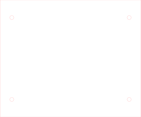
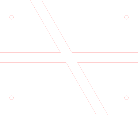
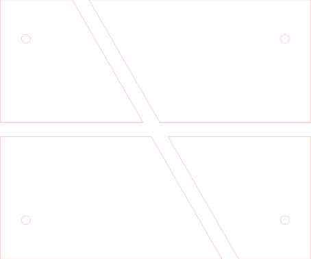
The shoe stops when its actual outline would enter the walls of the crossing. The red ghost shows the pose you requested. The round control can rotate at the centre; the pointed shoe encounters a wall. This is a quasistatic geometric constraint test, with no motor or simulated contact forces.
This 60° crossing is a separate development coupon. It is not a replacement cartridge for the main machine. The braider’s curved track, horn drive, adjacent carriers and transfer timing still require a coupled design and handoff test.
| Nominal quantity | Value |
|---|---|
| Plate / crossing | 120 × 100 mm / 60° |
| Guide slot / shoe | 8.6 mm / 8.0 mm wide; shoe 28 mm long |
| Retaining slot / neck | 5.6 mm / 4.8 mm diameter |
| Floor / roof gap | 0.3 mm each, before real fit adjustment |
Real maypole carriers use shaped guides and supporting horn components. US4774871A describes paired boat-shaped sliders; US20190380707A1 describes pivoting keels and carrier-retaining plates. These are architecture references. This original straight-crossing coupon does not reproduce or validate either complete machine.
The displayed motion advances in small translation/rotation increments and stops at the first detected intersection, then refines that contact. It is not a continuous-time rigid-body simulation or a proof that no other route exists in the full space of translations and rotations. The exported CAD separately checks a clear straight traverse.